前回、PRUによるBBBのペリフェラル操作の一例としてADCをリアルタイム制御を行うことにより音声レベルでのAD変換が行えることを示した。
今回はBBBのペリフェラルの一つEnhanced Capture (eCAP) ModuleをPRUにより制御を行い、音声レベルでのDA変換を実装する。
ターゲットスペックとしては以下。
・44.1KHzサンプリング出力
・11bit 2CHデータ出力
・44.1KHz 16bitステレオwavファイルの再生
少ない外付け部品によりステレオ音声の出力を実現させる。
先に断っておくが、11bit深度のPWM音源であるのでオーディオ鑑賞には耐えられない。
ではあるものの、電話音質は凌駕しているのでLPFを噛ませばMODEMの実験等に使えるかもしれない。
BBBにはPWMとして使用することができるペリフェラルとして以下がある。
・Enhanced PWM (ePWM) Module
・Enhanced Capture (eCAP) Module
・DMTimer(TIMER4~TIMER7)
これら3種のペリフェラルはPWM出力を行えるという点では同じだが、機能的には大きく異なる。
一番多機能なのはePWMで様々な波形を出力可能であるが、タイマビット長が16bitである。
TIMER4~TIMER7はタイマビット長は32bitであるものの基準クロックが25MHzとなっている。
eCAPは32bit長のタイマでかつ基準クロックが100MHzであるので、分解能では一番優れている。
また、eCAPはshadow registerを持ち、periodカウントタイミングで次のデータを自動で設定することができる。
44.1KHzはPRUからみて十分低速であるので、周期毎に次のデータを設定することができるので、PRUの制御によりDACを実装することができるわけだ。
今回、eCAP0とeCAP2をPRUから制御を行い、PWM DACの実装を試みる
eCAPはPulse-Width Modulation Subsystem (PWMSS)に含まれる3つのModuleの一つ、Enhanced Capture (eCAP) Moduleのこと。
PWMSSは0~2の3つ存在し、それぞれ一つのeCAPを持つので、AM335XXにはeCAP0~eCAP2の3つのeCAPが存在する。
eCAPは外部信号の周波数測定するためのCapture modeとPWM出力を行うためのAPWM modeの二つのmodeがある。
eCAP1_in_PWM1_outはBBBのピンヘッダに出ていないのでeCAP1を外部信号の周波数測定用途やPWM出力に用いることはできない。
従ってPWM出力に用いることができるのはeCAP0とeCAP2の二つである。
eCAP1は基準タイマの開始/停止や各種割り込みの生成は可能なので、内部基準タイマ用途専用となるだろう。
eCAPのAPWM modeでの動作概要は以下のようになる。
先ずAPRD_activeとAPRD_shadowにpreiod Pを設定する。
ACMP_activeとACMP_shadowにも$$0 < cmp < P$$の範囲内の初期値 cmp を与える。
この状態でTSCTRはフリーランカウンタとなっていて、起動するとTSCTRはカウントアップしてゆきPまでカウントすると再び0に戻りカウントアップを続ける。
TSCTRが0に戻るとき、PWMx_OUTは定められた極性に戻るとともに、APRD_shadowの内容をACMP_activeに、ACMP_shadowの内容をACMP_activeにそれぞれ自動コピーされる。
TSCTRがACMP_activeに一致した場合、PWMx_OUTの出力論理は反転する。
従って任意のタイミングでACMP_shadowを$$0 < cmp < P$$の範囲内の別の任意の値 cmp に更新すれば、次のperiodで希望するデューティ比に更新することができる。
音声出力用のDACとしてeCAPのAPWM modeを用いる為には、サンプリング周波数に合わせてperiod PをAPRDに設定し、周期毎にACMP_shadowをサンプリングデータで更新してゆけばよい。
動作概要は次の図のようになる。
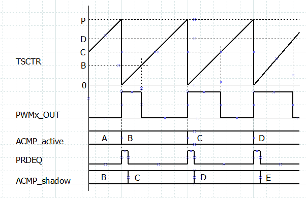
 APRDはいずれもPが設定されており、TSCTRは0からPまでをカウントし続ける。
ACMP_activeはAという値が、ACMP_shadowはBという値が設定されている。
TSCTRがPと一致したとき、PWMx_OUT出力は1となり、ACMP_activeにACMP_shadowの値がコピーされ、PRDEQ割り込みフラグがセットされる。
PRUはPRDEQ割り込みフラグをポーリングし、セットされていた場合リセットするとともに、ACMP_shadowを次のサンプリングデータの値Bで更新する。
ACMP_shadowの更新は次のTSCTRの0クリアまでの間に行えば良いのでポーリングで十分間に合うわけだ。
このようにACMP_shadowをサンプリング周期毎に逐次更新を行うことによりACMP_activeもサンプリング周期毎に更新されPWMx_OUTの出力デューティ比を更新することができる。
TSCTRの基準クロック周波数は100MHzであるので、所望周波数を44.1KHzとするならばAPRDに設定するperiod Pは2268が一つの候補となる。
$$\frac{100MHz/2268}{44.1KHz}100-100=-0.0188%$$となるので目的にもよるが許容範囲の誤差だろう。
period Pを2268にした場合での$$2268 > 2^x$$を満たす最大のxは11であるので、サンプリング分解能は11bitとした。
ePWMとeCAPはBBBでサポートされていて、以下以下のようにcapemgrにam33xx_pwmを与えることにより有効化することができる。
debian@beaglebone:~$ sudo -s
root@beaglebone:/home/debian# export SLOTS=/sys/devices/bone_capemgr.*/slots
root@beaglebone:/home/debian# echo am33xx_pwm > $SLOTS root@beaglebone:/home/debian#
device treeで設定するのはあくまでも各ペリフェラルレジスタをPRUから操作できるようにすることが目的。
上記を実施することにより、ePWM SS関連のレジスタを操作することができるようになる。
先に述べたようにeCAPにはeCAP0~eCAP2の3つがあるもののAPWM modeとして使えるのはeCAP0とeCAP2の二つ。
今回は以下の様に使う。
ecap0:P9_42
ecap2:P9_28
今回も前回までの環境が構築されている前提とする。
Beagle Bone BlackのPRUを学ぶ(その4)
Beagle Bone BlackのPRUを学ぶ(その3)
Beagle Bone BlackのPRUを学ぶ(その2)
Beagle Bone BlackのPRUを学ぶ(その1)
P9_42もP9_28も多少ややこしい。
P9_28はBBB内部でTDA19988 のAP1に結線されている。
BeagleBone Black Rev.Cのピンアサイン表参照。
デフォルトではP9_28は音声出力用途に設定されていて、device tree設定はBone-Black-HDMI/Bone-Black-HDMINの二つがloadされる。
よって、この二つをloadしないようにする必要がある。
詳細は以下を参照のこと。
TDA19988のAP1はTDA19988側からは音声入力ポートであり、未使用の場合でも比較的安全に操作できる。
P9_42はBBB内部でC18とB12に結線されていて、C12をeCAP2の出力として使うならばB12はhigh-Zに設定する必要がある。
以上を踏まえ、各GPIOを設定するためのdtsファイルを書いてみた。
/dts-v1/;
/plugin/;

/ {
    compatible = "ti,beaglebone", "ti,beaglebone-black";

    /* identification */
    part-number = "bone_JUNK_PWMDAC";
    version = "00A0";

    exclusive-use =
        /* pin header uses */
        "P9.42",    /* ecap0_P9_42:   [Bot C18] eCAP0_in_PWM0_out ! shared use ! */
                    /* gpio3_P9_42:   [Bot B12] gpio3[18]         ! shared use ! */
                    /* P9.42 is shared resource that is connected with both C18 and B12.
                       Since we wll use function on C18 as output pin, B12 has to be set to input(high-Z). */
        "P9.28",    /* ecap2_P9_28:   [Bot C12] eCAP2_in_PWM2_out_mux1 */

        /* the hardware IP uses */
        "eCAP0_in_PWM0_out",
        "eCAP2_in_PWM2_out";

    fragment@0 {
        target = <&am33xx_pinmux>;
        __overlay__ {
            ecap0_gpio: pinmux_ecap0_pins {
                pinctrl-single,pins = <
                    0x164 0x08  /* [Bot C18] (IDIS|OFF|MODE0)=(0 01 000) eCAP0_in_PWM0_out P9_42@ */
                >;
            };
            ecap2_gpio: pinmux_ecap2_pins {
                pinctrl-single,pins = <
                    0x19C 0x0c  /* [Bot C12] (IDIS|OFF|MODE4)=(0 01 100) eCAP2_in_PWM2_out_mux1 P9_28 */
                >;
            };
            gpio3_gpio: pinmux_gpio3_pins {
                pinctrl-single,pins = <
                    0x1A0 0x2f  /* [Bot B12] (IEN |OFF|MODE7)=(1 01 111) gpio3[18] P9_42@ */
                >;
            };
        };
    };

    fragment@1 {
        target = <&ocp>;
        __overlay__ {
            pwmdac_ecap0 {
                compatible      = "junk_pwmdac";
                pwms            = <&ecap0 0 0 1>;
                pwm-names       = "ECAP0";
                pinctrl-names   = "default";
                pinctrl-0       = <&ecap0_gpio>;
                enabled         = <1>;
                duty            = <0>;
                status          = "okay";
            };
            pwmdac_ecap2 {
                compatible      = "junk_pwmdac";
                pwms            = <&ecap2 0 0 1>;
                pwm-names       = "ECAP2";
                pinctrl-names   = "default";
                pinctrl-0       = <&ecap2_gpio>;
                enabled         = <1>;
                duty            = <0>;
                status          = "okay";
            };
            pwmdac_ecap0_gpio_helper: ecap0_gpio_helper {
                compatible      = "bone-pinmux-helper";
                pinctrl-names   = "default";
                pinctrl-0       = <&ecap0_gpio>;
                status          = "okay";
            };
            pwmdac_ecap2_gpio_helper: ecap2_gpio_helper {
                compatible      = "bone-pinmux-helper";
                pinctrl-names   = "default";
                pinctrl-0       = <&ecap2_gpio>;
                status          = "okay";
            };
            pwmdac_gpio3_gpio_helper: gpio3_gpio_helper {
                compatible      = "bone-pinmux-helper";
                pinctrl-names   = "default";
                pinctrl-0       = <&gpio3_gpio>;
                status          = "okay";
            };
        };
    };

    fragment@2 {
        target = <&pruss>;
        __overlay__ {
            status          = "okay";
        };
    };
};
このdtsファイルをbone-JUNK-PWMDAC-00A0.dtsという名前で/lib/firmwareに保存して以下のようにdtcでコンパイルする。
debian@beaglebone:/lib/firmware$ sudo dtc -@ -O dtb -o bone-JUNK-PWMDAC-00A0.dtbo bone-JUNK-PWMDAC-00A0.dts debian@beaglebone:/lib/firmware$ sudo reboot
念の為にリブートを行う。
再立ち上げ後root権限で以下を実行する。
debian@beaglebone:~$ sudo -s root@beaglebone:/home/debian# export SLOTS=/sys/devices/bone_capemgr.*/slots root@beaglebone:/home/debian# cat $SLOTS 0: 54:PF--- 1: 55:PF--- 2: 56:PF--- 3: 57:PF--- 4: ff:P-O-L Bone-LT-eMMC-2G,00A0,Texas Instrument,BB-BONE-EMMC-2G 5: ff:P-O-- Bone-Black-HDMI,00A0,Texas Instrument,BB-BONELT-HDMI 6: ff:P-O-- Bone-Black-HDMIN,00A0,Texas Instrument,BB-BONELT-HDMIN root@beaglebone:/home/debian# echo am33xx_pwm > $SLOTS root@beaglebone:/home/debian# echo bone-JUNK-PWMDAC > $SLOTS root@beaglebone:/home/debian# cat $SLOTS 0: 54:PF--- 1: 55:PF--- 2: 56:PF--- 3: 57:PF--- 4: ff:P-O-L Bone-LT-eMMC-2G,00A0,Texas Instrument,BB-BONE-EMMC-2G 5: ff:P-O-- Bone-Black-HDMI,00A0,Texas Instrument,BB-BONELT-HDMI 6: ff:P-O-- Bone-Black-HDMIN,00A0,Texas Instrument,BB-BONELT-HDMIN 7: ff:P-O-L Override Board Name,00A0,Override Manuf,am33xx_pwm 8: ff:P-O-L Override Board Name,00A0,Override Manuf,bone-JUNK-PWMDAC root@beaglebone:/home/debian# export PINS=/sys/kernel/debug/pinctrl/44e10800.pinmux/pins root@beaglebone:/home/debian# cat $PINS | grep 964 pin 89 (44e10964) 00000008 pinctrl-single root@beaglebone:/home/debian# cat $PINS | grep 99c pin 103 (44e1099c) 0000000c pinctrl-single root@beaglebone:/home/debian# cat $PINS | grep 9a0 pin 104 (44e109a0) 0000002f pinctrl-single root@beaglebone:/home/debian#
am33xx_pwmとbone-JUNK-PWMDACがloadされていて、意図したpin mux設定となっていることが確認できた。
eCAPを使用する為にはPWMSSのCLOCK設定が正常に行われている必要がある。
設定はPWMSSのCLKSTATUSにより確認ができる。
root@beaglebone:/home/debian# devmem2 0x4830000c w /dev/mem opened. Memory mapped at address 0xb6f71000. Value at address 0x4830000C (0xb6f7100c): 0x111 root@beaglebone:/home/debian# devmem2 0x4830200c w /dev/mem opened. Memory mapped at address 0xb6f32000. Value at address 0x4830200C (0xb6f3200c): 0x111 root@beaglebone:/home/debian# devmem2 0x4830400c w /dev/mem opened. Memory mapped at address 0xb6f79000. Value at address 0x4830400C (0xb6f7900c): 0x111 root@beaglebone:/home/debian#
am33xx_pwmをloadすることによりPWMSSの3つのmoduleであるePWM/eQEP/eCAP全てのクロック設定が行われるようだ。
尚、devmem2のインストール方法に関しては過去の記事を参照のこと。
devmem2とprudebugをインストール
PRUのソースコードを以下に晒す。
// pwm.p
.origin 0
.entrypoint PWM_SAMPLE
#include "pwmdac.hp"
// Our plan to use Registers
// R0-R4: temporary use
// R5: Previous command from host
// R6.w0: sampling data for right channel
// R6.w2: sampling data for left channel
// R7.w0: Buffer Index
// R8: Frame Counter
// R9.w0: mask pattern of ECFLG
// R10: Address of eCAP0_BASE
// R11: Address of eCAP0_BASE, but it may not be used.
// R12: Address of eCAP0_BASE
// R13.w0, 0x1000 // Harf size of RING_BUF or Offset for RING_BUF
// R13.w2, 0x2000 // Size of RING_BUF
// R14.w0, 0x0fff // Mask pattern for Harf of RING_BUF
// R14.w2, 0x1fff // Mask Pattern for all of RING_BUF
// R17-R20: always all ZERO
// I/F with Host
// CONST_PRUSHAREDRAM + 0x00: size 4Byte: Command from host.
// 0x00: Turn off
// 0x01: stop and init
// 0x02: run
// CONST_PRUSHAREDRAM + 0x04: size 4Byte: Status indication for host.
// 0x00: init
// 0x01: Stop
// 0x02: running
// 0x03: running but over-run.
// 0x04: running but under-run
// CONST_PRUSHAREDRAM + 0x08: size 4Byte: Frame Number Indication from host. it indicates number of harf of RING_BUF.
// even numbers indicates that current harf of RING_BUF is top harf.
// odd numbers indicates that current harf of RING_BUF is bottom harf.
// and then indicated number shows RING_BUF that is filled with new data.
// CONST_PRUSHAREDRAM + 0x0c: size 4Byte: Frame Number Indication to host. it indicates number of harf of RING_BUF.
// even number indicates that current harf of RING_BUF is top harf.
// odd number indicates that current harf of RING_BUF is bottom harf.
// and then indicated number shows RING_BUF that is consumed by pru.
// CONST_PRUSHAREDRAM + (0x1000 to 0x1fff): top harf of RING_BUF.
// CONST_PRUSHAREDRAM + (0x2000 to 0x3fff): bottom harf of RING_BUF.
PWM_SAMPLE:
// Make Constant values for registers
MOV r9.w0, 0x0040 // r9.w0 is mask pattern of ECFLG
MOV r10, eCAP0_BASE // r10 is Address of eCAP0_BASE
MOV r11, eCAP1_BASE // r11 is Address of eCAP1_BASE, but it may not be used.
MOV r12, eCAP2_BASE // r12 is Address of eCAP2_BASE
MOV r13.w0, 0x1000 // Harf size of RING_BUF
MOV r13.w2, 0x2000 // Size of RING_BUF
MOV r14.w0, 0x0fff // Mask pattern for Harf of RING_BUF
MOV r14.w2, 0x1fff // Mask Pattern for all of RING_BUF
MOV r17, 0x00000000 // r17 is always all ZERO
MOV r18, r17 // also r18-r20 are always all ZERO
MOV r19, r17 //
MOV r20, r17 //
// Enable OCP Master port
LBCO r0, CONST_PRUCFG, OFFSET_CFG_SYSCFG_REG, 4 // r0 = *(CONST_PRUCFG + OFFSET_CFG_SYSCFG_REG)
CLR r0, r0, 4 // Clear bit4 of r0 (Clear SYSCFG:STANDBY_INIT
// to enable OCP master port)
SBCO r0, CONST_PRUCFG, OFFSET_CFG_SYSCFG_REG, 4 // *(CONST_PRUCFG + OFFSET_CFG_SYSCFG_REG) = r0
// Init Indexs and Pointers of Constant tables
MOV r0, PRU0_CTRL_REG_BASE //
SBBO r17, r0, OFFSET_PRU_CTBIR0_REG, 4 // *(PRU0_CTRL_REG_BASE + OFFSET_PRU_CTBIR0_REG) = r17:0x00000000
// Set Fields C25_BLK_INDEX and C24_BLK_INDEX to 0.
MOV r1, 0x00000100 //
SBBO r1, r0, OFFSET_PRU_CTPPR0_REG, 4 // *(PRU0_CTRL_REG_BASE + OFFSET_PRU_CTPPR0_REG) = r1:0x00000100
// Set Fields C29_POINTER to 0x0000 and C28_POINTER to 0x0100.
// Unexpectedly, C28 is NOT dedicated for Shared PRU RAM,
// we can use C28 for PRU0/1 Local Data RAM if C28_POINTER
// in CTPPRx register is set to 0x0000/0x0020. So to use
// for Shared PRU RAM C28_POINTER must be set to 0x0100.
INIT_PWM:
// Init Indication params for/from Host
SBCO r17, CONST_PRUSHAREDRAM, 0x00, 4 // *(CONST_PRUSHAREDRAM + 0) = r17:0x00000000
SBCO r17, CONST_PRUSHAREDRAM, 0x04, 4 // *(CONST_PRUSHAREDRAM + 4) = r17:0x00000000
SBCO r17, CONST_PRUSHAREDRAM, 0x08, 4 // *(CONST_PRUSHAREDRAM + 8) = r17:0x00000000
SBCO r17, CONST_PRUSHAREDRAM, 0x0c, 4 // *(CONST_PRUSHAREDRAM + 12) = r17:0x00000000
SBCO r17, CONST_PRUSHAREDRAM, 0x10, 4 // *(CONST_PRUSHAREDRAM + 16) = r17:0x00000000
// just in case we check PWM_Subsystem_0, PWM_Subsystem_1 and PWM_Subsystem_2
MOV r2, PWM_Subsystem_0_BASE // r2 is Address of PWM_Subsystem_0_BASE
MOV r3, PWM_Subsystem_1_BASE // r3 is Address of PWM_Subsystem_1_BASE
MOV r4, PWM_Subsystem_2_BASE // r4 is Address of PWM_Subsystem_2_BASE
LBBO r0, r2, OFFSET_CLKSTATUS, 4 // r0 = *(r2:PWM_Subsystem_0_BASE + OFFSET_CLKSTATUS)
// 0x4830000c : 0x00000111
LBBO r0, r3, OFFSET_CLKSTATUS, 4 // r0 = *(r3:PWM_Subsystem_1_BASE + OFFSET_CLKSTATUS)
// 0x4830200c : 0x00000111
LBBO r0, r2, OFFSET_CLKSTATUS, 4 // r0 = *(r4:PWM_Subsystem_2_BASE + OFFSET_CLKSTATUS)
// 0x4830400c : 0x00000111
// CLKSTATUS Register is read-only and indicates Clock-Status.
// 9 ePWM_CLKSTOP_ACK R 0h
// This bit is the clkstop_req_ack status output of the ePWM module.
// 8 ePWM_CLK_EN_ACK R 0h
// This bit is the clk_en status output of the ePWM module.
// 7-6 RESERVED R 0h
// 5 eQEP_CLKSTOP_ACK R 0h
// This bit is the clkstop_req_ack status output of the eQEP module.
// 4 eQEP_CLK_EN_ACK R 0h
// This bit is the clk_en status output of the eQEP module.
// 3-2 RESERVED R 0h
// 1 eCAP_CLKSTOP_ACK R 0h
// This bit is the clkstop_req_ack status output of the eCAP module.
// 0 eCAP_CLK_EN_ACK R 0h
// This bit is the clk_en status output of the eCAP module.
PWM_INIT:
// init eCAP
// check REVID register for debug.
LBBO r1, r10, OFFSET_REVID, 4 // r1 = *(r10:eCAP0_BASE + OFFSET_REVID)
// 0x4830015c :
LBBO r1, r12, OFFSET_REVID, 4 // r1 = *(r12:eCAP2_BASE + OFFSET_REVID)
// 0x4830415c :
// REVID Register
// REVID register is read-only and fixed value as 0x44D22100.
// stop the running counter in TSCTR Register
MOV r1.w0, 0x0280 //
SBBO r1.w0, r10, OFFSET_ECCTL2, 2 // *(r10:eCAP0_BASE + OFFSET_ECCTL2) = r1.w0:0x0280
// 0x4830012a : 0x280
SBBO r1.w0, r12, OFFSET_ECCTL2, 2 // *(r12:eCAP2_BASE + OFFSET_ECCTL2) = r1.w0:0x0280
// 0x4830412a : 0x280
// we set mode to APWM and stop TSCTR counter.
// ECCTL2 Register
// 15-11 RESERVED R 0h
// * 10 APWMPOL R/W 0h APWM output polarity select.
// This is applicable only in APWM operating mode
// * 0h = Output is active high (Compare value defines high time)
// 1h = Output is active low (Compare value defines low time)
// * 9 CAP_APWM R/W 0h CAP/APWM operating mode select
// 0h = ECAP module operates in capture mode. This mode forces the
// following configuration.
// (a) Inhibits TSCTR resets via PRDEQ event.
// (b) Inhibits shadow loads on CAP1 and 2 registers.
// (c) Permits user to enable CAP1-4 register load.
// (d) ECAPn/APWMn pin operates as a capture input.
// * 1h = ECAP module operates in APWM mode. This mode forces the
// following configuration.
// (a) Resets TSCTR on PRDEQ event (period boundary).
// (b) Permits shadow loading on CAP1 and 2 registers.
// (c) Disables loading of time-stamps into CAP1-4 registers.
// (d) ECAPn/APWMn pin operates as a APWM output.
// * 8 SWSYNC R/W 0h Software-forced Counter (TSCTR) Synchronizing.
// This provides a convenient software method to synchronize some or
// all ECAP time bases.
// In APWM mode, the synchronizing can also be done via the PRDEQ event.
// Note: Selecting PRDEQ is meaningful only in APWM mode.
// However, you can choose it in CAP mode if you find doing
// so useful.
// * 0h = Writing a zero has no effect. Reading always returns a zero
// 1h = Writing a one forces a TSCTR shadow load of current ECAP
// module and any ECAP modules down-stream providing the
// SYNCO_SEL bits are 0,0. After writing a 1, this bit returns
// to a zero.
// * 7-6 SYNCO_SEL R/W 0h Sync-Out Select
// 0h = Select sync-in event to be the sync-out signal (pass through)
// 1h = Select PRDEQ event to be the sync-out signal
// * 2h = Disable sync out signal
// 3h = Disable sync out signal
// * 5 SYNCI_EN R/W 0h Counter (TSCTR) Sync-In select mode
// * 0h = Disable sync-in option
// 1h = Enable counter (TSCTR) to be loaded from CTRPHS register
// upon either a SYNCI signal or a S/W force event.
// 4 TSCTRSTOP R/W 0h Time Stamp (TSCTR) Counter Stop (freeze) Control
// * 0h = TSCTR stopped
// 1h = TSCTR free-running
// 3 RE-ARM R/W 0h One-Shot Re-Arming Control, that is, wait for
// stop trigger.
// Note: The re-arm function is valid in one shot or continuous mode.
// * 0h = Has no effect (reading always returns a 0)
// 1h = Arms the one-shot sequence as follows:
// 1) Resets the Mod4 counter to zero.
// 2) Unfreezes the Mod4 counter.
// 3) Enables capture register loads.
// 2-1 STOP_WRAP R/W 3h Stop value for one-shot mode.
// This is the number (between 1 and 4) of captures allowed to occur
// before the CAP (1 through 4) registers are frozen, that is, capture
// sequence is stopped.
// Wrap value for continuous mode.
// This is the number (between 1 and 4) of the capture register in which
// the circular buffer wraps around and starts again.
// Notes: STOP_WRAP is compared to Mod4 counter and, when
// equal, the following two actions occur.
// (1) Mod4 counter is stopped (frozen), and (2) Capture register loads
// are inhibited.
// In one-shot mode, further interrupt events are blocked until rearmed.
// * 0h = Stop after Capture Event 1 in one-shot mode. Wrap after
// Capture Event 1 in continuous mode.
// 1h = Stop after Capture Event 2 in one-shot mode. Wrap after
// Capture Event 2 in continuous mode.
// 2h = Stop after Capture Event 3 in one-shot mode. Wrap after
// Capture Event 3 in continuous mode.
// 3h = Stop after Capture Event 4 in one-shot mode. Wrap after
// Capture Event 4 in continuous mode.
// 0 CONT_ONESHT R/W 0h Continuous or one-shot mode control
// (applicable only in capture mode)
// * 0h = Operate in continuous mode
// 1h = Operate in one-shot mode
SBBO r17, r10, OFFSET_TSCTR, 4 // *(r10:eCAP0_BASE + OFFSET_TSCTR) = r17:0x00000000
// 0x48300100 : 0x0
SBBO r17, r12, OFFSET_TSCTR, 4 // *(r12:eCAP2_BASE + OFFSET_TSCTR) = r17:0x00000000
// 0x48304100 : 0x0
// TSCTR Register
SBBO r17, r10, OFFSET_CTRPHS, 4 // *(r10:eCAP0_BASE + OFFSET_CTRPHS) = r17:0x00000000
// 0x48300104 : 0x0
SBBO r17, r12, OFFSET_CTRPHS, 4 // *(r12:eCAP2_BASE + OFFSET_CTRPHS) = r17:0x00000000
// 0x48304104 : 0x0
// CTRPHS Register
MOV r1, PERIOD_44100 //
SBBO r1, r10, OFFSET_CAP1, 4 // *(r10:eCAP0_BASE + OFFSET_CAP1) = r1:PERIOD_44100
// 0x48300108 :
SBBO r1, r12, OFFSET_CAP1, 4 // *(r12:eCAP2_BASE + OFFSET_CAP1) = r1:PERIOD_44100
// 0x48304108 :
// CAP1 Register
SBBO r1, r10, OFFSET_CAP3, 4 // *(r10:eCAP0_BASE + OFFSET_CAP3) = r1:PERIOD_44100
// 0x48300110 :
SBBO r1, r12, OFFSET_CAP3, 4 // *(r12:eCAP2_BASE + OFFSET_CAP3) = r1:PERIOD_44100
// 0x48304110 :
// CAP3 Register
MOV r1, ZERO_LEVEL_44100 //
SBBO r1, r10, OFFSET_CAP2, 4 // *(r10:eCAP0_BASE + OFFSET_CAP2) = r1:ZERO_LEVEL_44100
// 0x4830010c :
SBBO r1, r12, OFFSET_CAP2, 4 // *(r12:eCAP2_BASE + OFFSET_CAP2) = r1:ZERO_LEVEL_44100
// 0x4830410c :
// CAP2 Register
SBBO r1, r10, OFFSET_CAP4, 4 // *(r10:eCAP0_BASE + OFFSET_CAP4) = r1:ZERO_LEVEL_44100
// 0x48300114 :
SBBO r1, r12, OFFSET_CAP4, 4 // *(r12:eCAP2_BASE + OFFSET_CAP4) = r1:ZERO_LEVEL_44100
// 0x48304114 :
// CAP4 Register
SBBO r17.w0, r10, OFFSET_ECCTL1, 2 // *(r10:eCAP0_BASE + OFFSET_ECCTL1) = r17.w0:0x0000
// 0x48300128 : 0x0
SBBO r17.w0, r12, OFFSET_ECCTL1, 2 // *(r12:eCAP2_BASE + OFFSET_ECCTL1) = r17.w0:0x0000
// 0x48304128 : 0x0
// ECCTL1 Register
// 15-14 FREE_SOFT R/W 0h Emulation Control
// 0h = TSCTR counter stops immediately on emulation suspend.
// 1h = TSCTR counter runs until = 0.
// 2h = TSCTR counter is unaffected by emulation suspend (Run Free).
// 3h = TSCTR counter is unaffected by emulation suspend (Run Free).
// 13-9 PRESCALE R/W 0h Event Filter prescale select ...
// 0h = Divide by 1 (i.e,. no prescale, by-pass the prescaler)
// 1h = Divide by 2
// 2h = Divide by 4
// 3h = Divide by 6
// 4h = Divide by 8
// 5h = Divide by 10
// 1Eh = Divide by 60
// 1Fh = Divide by 62
// 8 CAPLDEN R/W 0h Enable Loading of CAP1 to CAP4 registers on
// a capture event
// 0h = Disable CAP1 through 4 register loads at capture event time.
// 1h = Enable CAP1-4 register loads at capture event time.
// 7 CTRRST4 R/W 0h Counter Reset on Capture Event 4
// 0h = Do not reset counter on Capture Event 4 (absolute time
// stamp operation)
// 1h = Reset counter after Capture Event 4 time-stamp has been
// captured (used in difference mode operation)
// 6 CAP4POL R/W 0h Capture Event 4 Polarity select
// 0h = Capture Event 4 triggered on a rising edge (RE)
// 1h = Capture Event 4 triggered on a falling edge (FE)
// 5 CTRRST3 R/W 0h Counter Reset on Capture Event 3
// 0h = Do not reset counter on Capture Event 3 (absolute time stamp)
// 1h = Reset counter after Event 3 time-stamp has been captured
// (used in difference mode operation)
// 4 CAP3POL R/W 0h Capture Event 3 Polarity select
// 0h = Capture Event 3 triggered on a rising edge (RE)
// 1h = Capture Event 3 triggered on a falling edge (FE)
// 3 CTRRST2 R/W 0h Counter Reset on Capture Event 2
// 0h = Do not reset counter on Capture Event 2 (absolute time stamp)
// 1h = Reset counter after Event 2 time-stamp has been captured
// (used in difference mode operation)
// 2 CAP2POL R/W 0h Capture Event 2 Polarity select
// 0h = Capture Event 2 triggered on a rising edge (RE)
// 1h = Capture Event 2 triggered on a falling edge (FE)
// 1 CTRRST1 R/W 0h Counter Reset on Capture Event 1
// 0h = Do not reset counter on Capture Event 1 (absolute time stamp)
// 1h = Reset counter after Event 1 time-stamp has been captured
// (used in difference mode operation)
// 0 CAP1POL R/W 0h Capture Event 1 Polarity select
// 0h = Capture Event 1 triggered on a rising edge (RE)
// 1h = Capture Event 1 triggered on a falling edge (FE)
SBBO r17.w0, r10, OFFSET_ECEINT, 2 // *(r10:eCAP0_BASE + OFFSET_ECEINT) = r17.w0:0x0000
// 0x4830012c : 0x0
SBBO r9.w0, r12, OFFSET_ECEINT, 2 // *(r12:eCAP2_BASE + OFFSET_ECEINT) = r9.w0:0x0040
// 0x4830412c : 0x0
// ECEINT Register
// we will use both ecap0 and ecap2 as APWM, then these Period are same and
// these timings are almost same.
// so we will use only ECFLG:PRDEQ of ecap2, not of both.
// 15-8 RESERVED R 0h
// 7 CMPEQ R/W 0h Counter Equal Compare Interrupt Enable.
// 0h = Disable Compare Equal as an Interrupt source.
// 1h = Enable Compare Equal as an Interrupt source.
// * 6 PRDEQ R/W 0h Counter Equal Period Interrupt Enable.
// 0h = Disable Period Equal as an Interrupt source.
// * 1h = Enable Period Equal as an Interrupt source.
// 5 CNTOVF R/W 0h Counter Overflow Interrupt Enable.
// 0h = Disable counter Overflow as an Interrupt source.
// 1h = Enable counter Overflow as an Interrupt source.
// 4 CEVT4 R/W 0h Capture Event 4 Interrupt Enable.
// 0h = Disable Capture Event 4 as an Interrupt source.
// 1h = Enable Capture Event 4 as an Interrupt source.
// 3 CEVT3 R/W 0h Capture Event 3 Interrupt Enable.
// 0h = Disable Capture Event 3 as an Interrupt source.
// 1h = Enable Capture Event 3 as an Interrupt source.
// 2 CEVT2 R/W 0h Capture Event 2 Interrupt Enable.
// 0h = Disable Capture Event 2 as an Interrupt source.
// 1h = Enable Capture Event 2 as an Interrupt source.
// 1 CEVT1 R/W 0h Capture Event 1 Interrupt Enable .
// 0h = Disable Capture Event 1 as an Interrupt source.
// 1h = Enable Capture Event 1 as an Interrupt source.
// 0 RESERVED R 0h
MOV r1.w0, 0x00ff //
SBBO r1.w0, r10, OFFSET_ECCLR, 2 // *(r10:eCAP0_BASE + OFFSET_ECCLR) = r1.w0:0x00ff
// 0x48300130 : 0x0
SBBO r1.w0, r12, OFFSET_ECCLR, 2 // *(r12:eCAP2_BASE + OFFSET_ECCLR) = r1.w0:0x00ff
// 0x48304130 : 0x0
// ECCLR Register
// 15-8 RESERVED R 0h
// * 7 CMPEQ R/W 0h Counter Equal Compare Status Flag
// 0h = Writing a 0 has no effect. Always reads back a 0
// * 1h = Writing a 1 clears the CMPEQ flag condition
// * 6 PRDEQ R/W 0h Counter Equal Period Status Flag
// 0h = Writing a 0 has no effect. Always reads back a 0
// * 1h = Writing a 1 clears the PRDEQ flag condition
// * 5 CNTOVF R/W 0h Counter Overflow Status Flag
// 0h = Writing a 0 has no effect. Always reads back a 0
// * 1h = Writing a 1 clears the CNTOVF flag condition
// * 4 CEVT4 R/W 0h Capture Event 4 Status Flag
// 0h = Writing a 0 has no effect. Always reads back a 0.
// * 1h = Writing a 1 clears the CEVT3 flag condition.
// * 3 CEVT3 R/W 0h Capture Event 3 Status Flag
// 0h = Writing a 0 has no effect. Always reads back a 0.
// * 1h = Writing a 1 clears the CEVT3 flag condition.
// * 2 CEVT2 R/W 0h Capture Event 2 Status Flag
// 0h = Writing a 0 has no effect. Always reads back a 0.
// * 1h = Writing a 1 clears the CEVT2 flag condition.
// * 1 CEVT1 R/W 0h Capture Event 1 Status Flag
// 0h = Writing a 0 has no effect. Always reads back a 0.
// * 1h = Writing a 1 clears the CEVT1 flag condition.
// * 0 INT R/W 0h Global Interrupt Clear Flag
// 0h = Writing a 0 has no effect. Always reads back a 0.
// * 1h = Writing a 1 clears the INT flag and enable further interrupts
// to be generated if any of the event flags are set to 1.
LBBO r1.w0, r10, OFFSET_ECFLG, 2 // r1.w0 = *(r10:eCAP0_BASE + OFFSET_ECFLG)
// 0x4830012e : 0x0
LBBO r1.w0, r12, OFFSET_ECFLG, 2 // r1.w0 = *(r12:eCAP2_BASE + OFFSET_ECFLG)
// 0x4830412e : 0x0
// ECFLG Register
// 15-8 RESERVED R 0h
// 7 CMPEQ R 0h Compare Equal Compare Status Flag.
// This flag is only active in APWM mode.
// 0h = Indicates no event occurred
// 1h = Indicates the counter (TSCTR) reached the compare register
// value (ACMP)
// 6 PRDEQ R 0h Counter Equal Period Status Flag.
// This flag is only active in APWM mode.
// 0h = Indicates no event occurred
// 1h = Indicates the counter (TSCTR) reached the period register
// value (APRD) and was reset.
// 5 CNTOVF R 0h Counter Overflow Status Flag.
// This flag is active in CAP and APWM mode.
// 0h = Indicates no event occurred.
// 1h = Indicates the counter (TSCTR) has made the transition from
// 0xFFFFFFFF to 0x00000000
// 4 CEVT4 R 0h Capture Event 4 Status Flag This flag is only active
// in CAP mode.
// 0h = Indicates no event occurred
// 1h = Indicates the fourth event occurred at ECAPn pin
// 3 CEVT3 R 0h Capture Event 3 Status Flag.
// This flag is active only in CAP mode.
// 0h = Indicates no event occurred.
// 1h = Indicates the third event occurred at ECAPn pin.
// 2 CEVT2 R 0h Capture Event 2 Status Flag.
// This flag is only active in CAP mode.
// 0h = Indicates no event occurred.
// 1h = Indicates the second event occurred at ECAPn pin.
// 1 CEVT1 R 0h Capture Event 1 Status Flag.
// This flag is only active in CAP mode.
// 0h = Indicates no event occurred.
// 1h = Indicates the first event occurred at ECAPn pin.
// 0 INT R 0h Global Interrupt Status Flag
// 0h = Indicates no interrupt generated.
// 1h = Indicates that an interrupt was generated
MOV r8, r17 // r8:FrameCounter = r17.w0:0x0000
SBCO r8, CONST_PRUSHAREDRAM, 0x0c, 4 // *(CONST_PRUSHAREDRAM + 12) = r8:FrameCounter
MOV r0, 1 //
SBCO r0, CONST_PRUSHAREDRAM, 0x04, 4 // *(CONST_PRUSHAREDRAM + 4) = r0:0x00000001
MOV r31.b0, PRU0_ARM_INTERRUPT+16 // Send notification to Host
// It means that pwm init is done.
// we have just done initialization of ragisters.
// after that, we wait the indication to turn on from host.
WAIT_TURN_ON:
// check command from host with shared mem
LBCO r0, CONST_PRUSHAREDRAM, 0x00, 4 // r0 = *(CONST_PRUSHAREDRAM + 0)
QBGT WAIT_TURN_ON, r0, 2 // if 2 > r0:Command_from_host then goto WAIT_TURN_ON
MOV r0, 2 //
SBCO r0, CONST_PRUSHAREDRAM, 0x04, 4 // *(CONST_PRUSHAREDRAM + 4) = r0:0x00000002
// start the running counter in TSCTR Register
MOV r1.w0, 0x0290 //
SBBO r1.w0, r10, OFFSET_ECCTL2, 2 // *(r10:eCAP0_BASE + OFFSET_ECCTL2) = r1.w0:0x0290
// 0x4830012a : 0x290
SBBO r1.w0, r12, OFFSET_ECCTL2, 2 // *(r12:eCAP2_BASE + OFFSET_ECCTL2) = r1.w0:0x0290
// 0x4830412a : 0x290
// we set ECCTL2:TSCTRSTOP to Enable to start TSCTR as runnning counter.
// ECCTL2 Register
// 4 TSCTRSTOP R/W 0h Time Stamp (TSCTR) Counter Stop (freeze) Control
// 0h = TSCTR stopped
// * 1h = TSCTR free-running
// we do not change other fileds in this register.
AND r0, r8, 1 //
MOV r7.w0, r17.w0 // r7.w0:LoopCounter = r17.w0:0x0000
QBEQ WAIT_TURN_ON1, r0, 0 // if 0x00000000 == (CurrentFrameNum & 0x00000001) then goto WAIT_TURN_ON1
MOV r7.w0, r13.w0 // else r7.w0:LoopCounter = r13.w0:0x1000
WAIT_TURN_ON1:
MOV r5, 1 // r5:PreviousCommand = 0x1
//endless main loop
MAIN_LOOP:
LBCO r3, CONST_PRUSHAREDRAM, 0x00, 4 // r3 = *(CONST_PRUSHAREDRAM + 0)
// r3 is current command from host
QBEQ PWM_INIT, r3, 0 // if 0 == r3:Command_from_host then goto PWM_INIT
// we check the ECFLG:PRDEQ in eCAP2
LBBO r1.w0, r12, OFFSET_ECFLG, 2 // r1.w0 = *(r12:eCAP2_BASE + OFFSET_ECFLG)
AND r0.w0, r1.w0, r9.w0 // r0.w0 = r1.w0:ECFLG & r9.w0:0x0040
QBEQ MAIN_LOOP, r0.w0, r17.w0 // if r17.w0:0x0000 == r0.w0 then goto MAIN_LOOP
// Now ECFLG:PRDEQ in eCAP2 has been set, so we clear it
SBBO r9.w0, r12, OFFSET_ECCLR, 2 // *(r12:eCAP2_BASE + OFFSET_ECCLR) = r9.w0:0x0040
// check command from host with shared mem
QBLT RUN_STATE, r5, 1 // if 1 < r5:PreviousCommand then goto RUN_STATE
STOP_STATE:
MOV r6.w0,CENTER_OF_11b_SAMPLE // r6.w0:samplingDataForRightChannel = CENTER_OF_11b_SAMPLE:1024
MOV r6.w2,CENTER_OF_11b_SAMPLE // r6.w0:samplingDataForLeftChannel = CENTER_OF_11b_SAMPLE:1024
// 1024 means zero level of 11bit sampling data.
QBGT SET_SAMPLING_DATA,r3,2 // if 2 > r3:Command_from_host then goto SET_SAMPLING_DATA
MOV r5, r3 // update r5:PreviousCommand to NewCommand:0x02
SBCO r3, CONST_PRUSHAREDRAM, 0x04, 4 // *(CONST_PRUSHAREDRAM + 4) = r3
JMP GET_SAMPLING_DATA
RUN_STATE:
QBLT GET_SAMPLING_DATA,r3,1 // if 1 < r3:Command_from_host then goto GET_SAMPLING_DATA
STOP_CMD_IN_RUN_STATE:
MOV r5, r3 // update r5:PreviousCommand to NewCommand:0x01
SBCO r3, CONST_PRUSHAREDRAM, 0x04, 4 // *(CONST_PRUSHAREDRAM + 4) = r3
MOV r6.w0,CENTER_OF_11b_SAMPLE // r6.w0:samplingDataForRightChannel = CENTER_OF_11b_SAMPLE:1024
MOV r6.w2,CENTER_OF_11b_SAMPLE // r6.w0:samplingDataForLeftChannel = CENTER_OF_11b_SAMPLE:1024
JMP SET_SAMPLING_DATA
GET_SAMPLING_DATA:
// we get sampling data.
ADD r0.w0, r7.w0, r13.w0 // r0.w0 = r7.w0:LoopCounter + r13.w0:RingBufferOfset:0x1000
LBCO r6, CONST_PRUSHAREDRAM, r0.w0, 4 // r6 = *(CONST_PRUSHAREDRAM + r0.w0)
// r6.w0 is sampling data for right channel
// r6.w2 is sampling data for left channel
// we count-up Ring Buffer Index,
ADD r7.w0, r7.w0, 4 // r7.w0:BufferIndex = r7.w0:BufferIndex + 4
AND r0.w0, r7.w0, r14.w0
QBNE SET_SAMPLING_DATA, r0.w0, 0 // if 0 != (r7.w0:BufferIndex & r14.w0:0x0fff) then goto SET_SAMPLING_DATA
// we update frame number in indications and send notification to host with interrupt
// because current frame has just been consumed.
AND r7.w0, r7.w0, r14.w2 // r7.w0:BufferIndex = r7.w0 & r14.w2:0x1fff
ADD r8, r8, 1 // r8:FrameCounter += 1
SBCO r8, CONST_PRUSHAREDRAM, 0x0c, 4 // *(CONST_PRUSHAREDRAM + 12) = r8
MOV r0.w0, r7.w0
MOV r0.w2, r17.w2
SBCO r0, CONST_PRUSHAREDRAM, 0x10, 4 // *(CONST_PRUSHAREDRAM + 16) = r0
MOV r31.b0, PRU0_ARM_INTERRUPT+16 // Send notification to Host
// It means that half of RING_BUF has been comsumed
// as DAC sampling data.
SET_SAMPLING_DATA:
MOV r0.w0, MAX_OF_11b_SAMPLE // r0.w0 = MAX_OF_11b_SAMPLE:2047
QBGE SET_SAMPLING_DATA1, r6.w0, r0.w0 // if r0.w0:2047 >= r6.w0:RightChannelData then goto SET_SAMPLING_DATA1
MOV r6.w0, r0.w0 // else r6.w0:RightChannelData = r0.w0:MAX_OF_11b_SAMPLE
SET_SAMPLING_DATA1:
QBGE SET_SAMPLING_DATA2, r6.w2, r0.w0 // if r0.w0:2047 >= r6.w2:LeftChannelData then goto SET_SAMPLING_DATA2
MOV r6.w2, r0.w0 // else r6.w2:LeftChannelData = r0.w0:MAX_OF_11b_SAMPLE
SET_SAMPLING_DATA2:
ADD r6.w0, r6.w0, OFFSET_ZERO_LEVEL //
ADD r6.w2, r6.w2, OFFSET_ZERO_LEVEL //
MOV r0.w2, r17.w0 //
MOV r0.w0, r6.w0 //
SBBO r0, r10, OFFSET_CAP4, 4 // *(r10:eCAP0_BASE + OFFSET_CAP4) = r0:RightChannelData
// 0x48300114 :
MOV r0.w0, r6.w2 //
SBBO r0, r12, OFFSET_CAP4, 4 // *(r12:eCAP2_BASE + OFFSET_CAP4) = r0:LeftChannelData
// 0x48304114 :
// CAP4 Register is shadow-register of CAP2 compare-register
JMP MAIN_LOOP // goto MAIN_LOOP
同じくPRUのincludeファイル。
// pwm.hp
#ifndef _PRU_PWM_
#define _PRU_PWM_
// ***************************************
// * Global Macro definitions *
// ***************************************
#define PRU0_PRU1_INTERRUPT 17
#define PRU1_PRU0_INTERRUPT 18
#define PRU0_ARM_INTERRUPT 19
#define PRU1_ARM_INTERRUPT 20
#define ARM_PRU0_INTERRUPT 21
#define ARM_PRU1_INTERRUPT 22
#define CONST_PRUCFG C4
#define CONST_PRUD0RAM C24
#define CONST_PRUD1RAM C25
#define CONST_PRUSHAREDRAM C28
#define CONST_DDR C31
#define PRU0_CTRL_REG_BASE 0x00022000
#define OFFSET_PRU_CONTROL_REG 0x00
#define OFFSET_PRU_STATUS_REG 0x04
// 5 SUB_MWAIT
// Status bit for wait state.
// 0 = Ready for Transaction
// 1 = Wait until 0
// 4 STANDBY_INIT
// 1 = Initiate standby sequence.
// 0 = Ready for Transaction
// 3-2 STANDBY_MODE
// 0h = Force standby mode: Initiator unconditionally
// in standby (standby = 1).
// 1h = No standby mode: Initiator unconditionally out
// of standby (standby = 0).
// 2h = Smart standby mode: Standby requested by initiator
// depending on internal conditions.
// 3h = Reserved.
// 1-0 IDLE_MODE
// 0h = Force-idle mode.
// 1h = No-idle mode.
// 2h = Smart-idle mode.
// 3h = Reserved.
#define OFFSET_PRU_WAKEUP_EN_REG 0x08
#define OFFSET_PRU_CYCLE_REG 0x0C
#define OFFSET_PRU_STALL_REG 0x10
#define OFFSET_PRU_CTBIR0_REG 0x20
// 23-16 C25_BLK_INDEX (PRU1/0 Local Data)
// 7-0 C24_BLK_INDEX (PRU0/1 Local Data)
#define OFFSET_PRU_CTBIR1_REG 0x24
// 23-16 C27_BLK_INDEX (MII_RT (local))
// 7-0 C26_BLK_INDEX (IEP (local))
#define OFFSET_PRU_CTPPR0_REG 0x28
// 31-16 C29_POINTER (TPCC)
// 15-0 C28_POINTER (Shared PRU RAM (local))
#define OFFSET_PRU_CTPPR1_REG 0x2C
// 31-16 C31_POINTER (EMIF0 DDR Base)
// 15-0 C30_POINTER (L3 OCMC0)
#define PRU_ICSS_CFG_REG_BASE 0x00026000
#define OFFSET_CFG_REVID_REG 0x00
#define OFFSET_CFG_SYSCFG_REG 0x04
// 5 SUB_MWAIT
// Status bit for wait state.(Read only)
// 0 = Ready for Transaction
// 1 = Wait until 0
// 4 STANDBY_INIT
// 1 = Initiate standby sequence.
// 0 = Enable OCP master ports.
// 3-2 STANDBY_MODE
// 0h = Force standby mode: Initiator unconditionally
// in standby (standby = 1).
// 1h = No standby mode: Initiator unconditionally out
// of standby (standby = 0).
// 2h = Smart standby mode: Standby requested by initiator
// depending on internal conditions.
// 3h = Reserved.
// 1-0 IDLE_MODE
// 0h = Force-idle mode.
// 1h = No-idle mode.
// 2h = Smart-idle mode.
// 3h = Reserved.
#define OFFSET_CFG_GPCFG0_REG 0x08
// 25 PRU0_GPO_SH_SEL
// Defines which shadow register is currently getting used
// for GPO shifting.(Read only)
// 0 = gpo_sh0 is selected
// 1 = gpo_sh1 is selected
// 24-20 PRU0_GPO_DIV1
// Divisor value (divide by PRU0_GPO_DIV1 + 1).
// 0h = div 1.0.
// 1h = div 1.5.
// 2h = div 2.0.
// ..
// 1eh = div 16.0.
// 1fh = reserved.
// 19-15 PRU0_GPO_DIV0
// Same as PRU0_GPO_DIV1
// 14 PRU0_GPO_MODE
// 0 = Direct output mode
// 1 = Serial output mode
// 13 PRU0_GPI_SB
// Start Bit event for 28-bit shift mode.
// PRU0_GPI_SB (pru0_r31_status[29]) is set when first capture
// of a 1 on pru0_r31_status[0].
// Read 1: Start Bit event occurred.
// Read 0: Start Bit event has not occurred.
// Write 1: Will clear PRU0_GPI_SB and clear the whole
// shift register.
// Write 0: No Effect.
// 12-8 PRU0_GPI_DIV1
// Divisor value (divide by PRU0_GPI_DIV1 + 1).
// 0h = div 1.0.
// 1h = div 1.5.
// 2h = div 2.0.
// ..
// 1eh = div 16.0.
// 1fh = reserved.
// 7-3 PRU0_GPI_DIV0
// Same as PRU0_GPI_DIV1
// 2 PRU0_GPI_CLK_MODE
// Parallel 16-bit capture mode clock edge.
// 0 = Use the positive edge of pru0_r31_status[16]
// 1 = Use the negative edge of pru0_r31_status[16]
// 1-0 PRU0_GPI_MODE
// 0h = Direct connection mode.
// 1h = 16-bit parallel capture mode.
// 2h = 28-bit shift mode.
// 3h = Mii_rt mode.
#define OFFSET_CFG_GPCFG1_REG 0x0C
// Fields are Same as GPCFG0_REG, buf GPCFG1_REG is for PRU1.
#define OFFSET_CFG_CGR_REG 0x10
#define OFFSET_CFG_ISRP_REG 0x14
#define OFFSET_CFG_ISP_REG 0x18
#define OFFSET_CFG_IESP_REG 0x1C
#define OFFSET_CFG_IECP_REG 0x20
#define OFFSET_CFG_PMAO_REG 0x28
#define OFFSET_CFG_MII_RT_REG 0x2C
#define OFFSET_CFG_IEPCLK_REG 0x30
#define OFFSET_CFG_SPP_REG 0x34
#define OFFSET_CFG_PIN_MX_REG 0x40
// Address for the Constant table Block Index Register (CTBIR)
#define CTBIR 0x22020
// Address for the Constant table Programmable Pointer Register 0(CTPPR_0)
#define CTPPR_0 0x22028
// Address for the Constant table Programmable Pointer Register 1(CTPPR_1)
#define CTPPR_1 0x2202C
// CM_PER related registers define
#define CM_PER_BASE 0x44E00000 // Clock Module Peripheral Registers
#define OFFSET_CM_PER_L4LS_CLKSTCTRL 0x000
#define OFFSET_CM_PER_L3S_CLKSTCTRL 0x004
#define OFFSET_CM_PER_L3_CLKSTCTRL 0x00C
#define OFFSET_CM_PER_CPGMAC0_CLKCTRL 0x014
#define OFFSET_CM_PER_LCDC_CLKCTRL 0x018
#define OFFSET_CM_PER_USB0_CLKCTRL 0x01C
#define OFFSET_CM_PER_TPTC0_CLKCTRL 0x024
#define OFFSET_CM_PER_EMIF_CLKCTRL 0x028
#define OFFSET_CM_PER_OCMCRAM_CLKCTRL 0x02C
#define OFFSET_CM_PER_GPMC_CLKCTRL 0x030
#define OFFSET_CM_PER_MCASP0_CLKCTRL 0x034
#define OFFSET_CM_PER_UART5_CLKCTRL 0x038
#define OFFSET_CM_PER_MMC0_CLKCTRL 0x03C
#define OFFSET_CM_PER_ELM_CLKCTRL 0x040
#define OFFSET_CM_PER_I2C2_CLKCTRL 0x044
#define OFFSET_CM_PER_I2C1_CLKCTRL 0x048
#define OFFSET_CM_PER_SPI0_CLKCTRL 0x04C
#define OFFSET_CM_PER_SPI1_CLKCTRL 0x050
#define OFFSET_CM_PER_L4LS_CLKCTRL 0x060
#define OFFSET_CM_PER_MCASP1_CLKCTRL 0x068
#define OFFSET_CM_PER_UART1_CLKCTRL 0x06C
#define OFFSET_CM_PER_UART2_CLKCTRL 0x070
#define OFFSET_CM_PER_UART3_CLKCTRL 0x074
#define OFFSET_CM_PER_UART4_CLKCTRL 0x078
#define OFFSET_CM_PER_TIMER7_CLKCTRL 0x07C // timer7
#define OFFSET_CM_PER_TIMER2_CLKCTRL 0x080
#define OFFSET_CM_PER_TIMER3_CLKCTRL 0x084
#define OFFSET_CM_PER_TIMER4_CLKCTRL 0x088 // timer4
#define OFFSET_CM_PER_GPIO1_CLKCTRL 0x0AC
#define OFFSET_CM_PER_GPIO2_CLKCTRL 0x0B0
#define OFFSET_CM_PER_GPIO3_CLKCTRL 0x0B4
#define OFFSET_CM_PER_TPCC_CLKCTRL 0x0BC
#define OFFSET_CM_PER_DCAN0_CLKCTRL 0x0C0
#define OFFSET_CM_PER_DCAN1_CLKCTRL 0x0C4
#define OFFSET_CM_PER_EPWMSS1_CLKCTRL 0x0CC // epwmss1
#define OFFSET_CM_PER_EPWMSS0_CLKCTRL 0x0D4 // epwmss0
#define OFFSET_CM_PER_EPWMSS2_CLKCTRL 0x0D8 // epwmss2
#define OFFSET_CM_PER_L3_INSTR_CLKCTRL 0x0DC
#define OFFSET_CM_PER_L3_CLKCTRL 0x0E0
#define OFFSET_CM_PER_IEEE5000_CLKCTRL 0x0E4
#define OFFSET_CM_PER_PRU_ICSS_CLKCTRL 0x0E8 // pru_icss
#define OFFSET_CM_PER_TIMER5_CLKCTRL 0x0EC // timer5
#define OFFSET_CM_PER_TIMER6_CLKCTRL 0x0F0 // timer6
#define OFFSET_CM_PER_MMC1_CLKCTRL 0x0F4
#define OFFSET_CM_PER_MMC2_CLKCTRL 0x0F8
#define OFFSET_CM_PER_TPTC1_CLKCTRL 0x0FC
#define OFFSET_CM_PER_TPTC2_CLKCTRL 0x100
#define OFFSET_CM_PER_SPINLOCK_CLKCTRL 0x10C
#define OFFSET_CM_PER_MAILBOX0_CLKCTRL 0x110
#define OFFSET_CM_PER_L4HS_CLKSTCTRL 0x11C
#define OFFSET_CM_PER_L4HS_CLKCTRL 0x120
#define OFFSET_CM_PER_OCPWP_L3_CLKSTCTRL 0x12C
#define OFFSET_CM_PER_OCPWP_CLKCTRL 0x130
#define OFFSET_CM_PER_PRU_ICSS_CLKSTCTRL 0x140 // pru_icss_clk
#define OFFSET_CM_PER_CPSW_CLKSTCTRL 0x144
#define OFFSET_CM_PER_LCDC_CLKSTCTRL 0x148
#define OFFSET_CM_PER_CLKDIV32K_CLKCTRL 0x14C
#define OFFSET_CM_PER_CLK_24MHZ_CLKSTCTRL 0x150
// CM_DPLL related registers define
#define CM_DPLL_BASE 0x44E00500 // Clock Module PLL Registers
#define OFFSET_CLKSEL_TIMER7_CLK 0x04 // Selects the Mux select line for TIMER7 clock
#define OFFSET_CLKSEL_TIMER2_CLK 0x08 // Selects the Mux select line for TIMER2 clock
#define OFFSET_CLKSEL_TIMER3_CLK 0x0C // Selects the Mux select line for TIMER3 clock
#define OFFSET_CLKSEL_TIMER4_CLK 0x10 // Selects the Mux select line for TIMER4 clock
#define OFFSET_CM_MAC_CLKSEL 0x14 // Selects the clock divide ration for MII clock
#define OFFSET_CLKSEL_TIMER5_CLK 0x18 // Selects the Mux select line for TIMER5 clock
#define OFFSET_CLKSEL_TIMER6_CLK 0x1C // Selects the Mux select line for TIMER6 clock
#define OFFSET_ CM_CPTS_RFT_CLKSEL 0x20 // Selects the Mux select line for CPTS RFT clock
#define OFFSET_CLKSEL_TIMER1MS_CLK 0x28 // Selects the Mux select line for TIMER1 clock
#define OFFSET_CLKSEL_GFX_FCLK 0x2C // Selects the divider value for GFX clock
#define OFFSET_CLKSEL_PRU_ICSS_OCP_CLK 0x30 // Controls the Mux select line for PRU-ICSS OCP clock
#define OFFSET_CLKSEL_LCDC_PIXEL_CLK 0x34 // Controls the Mux select line for LCDC PIXEL clock
#define OFFSET_CLKSEL_WDT1_CLK 0x38 // Selects the Mux select line for Watchdog1 clock
#define OFFSET_CLKSEL_GPIO0_DBCLK 0x3C // Selects the Mux select line for GPIO0 debounce clock
// PWMSS related registers define
#define PWM_Subsystem_0_BASE 0x48300000 // PWMSS0 Configuration Registers
#define PWM_Subsystem_1_BASE 0x48302000 // PWMSS1 Configuration Registers
#define PWM_Subsystem_2_BASE 0x48304000 // PWMSS2 Configuration Registers
#define OFFSET_IDVER 0x00 // IDVER IP Revision Register
#define OFFSET_SYSCONFIG 0x04 // SYSCONFIG System Configuration Register Section 15.1.2.2
#define OFFSET_CLKCONFIG 0x08 // CLKCONFIG Clock Configuration Register Section 15.1.2.3
#define OFFSET_CLKSTATUS 0x0C // CLKSTATUS Clock Status Register Section 15.1.2.4
// ePWM related registers define
#define ePWM0_BASE 0x48300200 // PWMSS ePWM0 Registers
#define ePWM1_BASE 0x48302200 // PWMSS ePWM1 Registers
#define ePWM2_BASE 0x48304200 // PWMSS ePWM2 Registers
#define OFFSET_TBCTL 0x00 // TBCTL Time-Base Control Register Section 15.2.4.1
#define OFFSET_TBSTS 0x02 // TBSTS Time-Base Status Register Section 15.2.4.2
#define OFFSET_TBPHSHR 0x04 // TBPHSHR Extension for HRPWM Phase Register Section 15.2.4.3
#define OFFSET_TBPHS 0x06 // TBPHS Time-Base Phase Register Section 15.2.4.4
#define OFFSET_TBCNT 0x08 // TBCNT Time-Base Counter Register Section 15.2.4.5
#define OFFSET_TBPRD 0x0A // TBPRD Time-Base Period Register Section 15.2.4.6
#define OFFSET_CMPCTL 0x0E // CMPCTL Counter-Compare Control Register Section 15.2.4.7
#define OFFSET_CMPAHR 0x10 // CMPAHR Extension for HRPWM Counter-Compare A Register Section 15.2.4.8
#define OFFSET_CMPA 0x12 // CMPA Counter-Compare A Register Section 15.2.4.9
#define OFFSET_CMPB 0x14 // CMPB Counter-Compare B Register Section 15.2.4.10
#define OFFSET_AQCTLA 0x16 // AQCTLA Action-Qualifier Control Register for Output A (EPWMxA) Section 15.2.4.11
#define OFFSET_AQCTLB 0x18 // AQCTLB Action-Qualifier Control Register for Output B (EPWMxB) Section 15.2.4.12
#define OFFSET_AQSFRC 0x1A // AQSFRC Action-Qualifier Software Force Register Section 15.2.4.13
#define OFFSET_AQCSFRC 0x1C // AQCSFRC Action-Qualifier Continuous S/W Force Register Set Section 15.2.4.14
#define OFFSET_DBCTL 0x1E // DBCTL Dead-Band Generator Control Register Section 15.2.4.15
#define OFFSET_DBRED 0x20 // DBRED Dead-Band Generator Rising Edge Delay Count Register Section 15.2.4.16
#define OFFSET_DBFED 0x22 // DBFED Dead-Band Generator Falling Edge Delay Count Register Section 15.2.4.17
#define OFFSET_TZSEL 0x24 // TZSEL Trip-Zone Select Register Section 15.2.4.18
#define OFFSET_TZCTL 0x28 // TZCTL Trip-Zone Control Register Section 15.2.4.19
#define OFFSET_TZEINT 0x2A // TZEINT Trip-Zone Enable Interrupt Register Section 15.2.4.20
#define OFFSET_TZFLG 0x2C // TZFLG Trip-Zone Flag Register Section 15.2.4.21
#define OFFSET_TZCLR 0x2E // TZCLR Trip-Zone Clear Register Section 15.2.4.22
#define OFFSET_TZFRC 0x30 // TZFRC Trip-Zone Force Register Section 15.2.4.23
#define OFFSET_ETSEL 0x32 // ETSEL Event-Trigger Selection Register Section 15.2.4.24
#define OFFSET_ETPS 0x34 // ETPS Event-Trigger Pre-Scale Register Section 15.2.4.25
#define OFFSET_ETFLG 0x36 // ETFLG Event-Trigger Flag Register Section 15.2.4.26
#define OFFSET_ETCLR 0x38 // ETCLR Event-Trigger Clear Register Section 15.2.4.27
#define OFFSET_ETFRC 0x3A // ETFRC Event-Trigger Force Register Section 15.2.4.28
#define OFFSET_PCCTL 0x3C // PCCTL PWM-Chopper Control Register Section 15.2.4.29
#define OFFSET_HRCNFG 0xC0 // HRCNFG HRPWM configuration register (HRCNFG) Section 15.2.4.30
// eCAP related registers define
#define eCAP0_BASE 0x48300100 // PWMSS eCAP0 Registers
#define eCAP1_BASE 0x48302100 // PWMSS eCAP1 Registers
#define eCAP2_BASE 0x48304100 // PWMSS eCAP2 Registers
#define OFFSET_TSCTR 0x00 // TSCTR Time-Stamp Counter Register Section 15.3.4.1.1
#define OFFSET_CTRPHS 0x04 // CTRPHS Counter Phase Offset Value Register Section 15.3.4.1.2
#define OFFSET_CAP1 0x08 // CAP1 Capture 1 Register Section 15.3.4.1.3
#define OFFSET_CAP2 0x0C // CAP2 Capture 2 Register Section 15.3.4.1.4
#define OFFSET_CAP3 0x10 // CAP3 Capture 3 Register Section 15.3.4.1.5
#define OFFSET_CAP4 0x14 // CAP4 Capture 4 Register Section 15.3.4.1.6
#define OFFSET_ECCTL1 0x28 // ECCTL1 Capture Control Register 1 Section 15.3.4.1.7
#define OFFSET_ECCTL2 0x2A // ECCTL2 Capture Control Register 2 Section 15.3.4.1.8
#define OFFSET_ECEINT 0x2C // ECEINT Capture Interrupt Enable Register Section 15.3.4.1.9
#define OFFSET_ECFLG 0x2E // ECFLG Capture Interrupt Flag Register Section 15.3.4.1.10
#define OFFSET_ECCLR 0x30 // ECCLR Capture Interrupt Clear Register Section 15.3.4.1.11
#define OFFSET_ECFRC 0x32 // ECFRC Capture Interrupt Force Register Section 15.3.4.1.12
#define OFFSET_REVID 0x5C // REVID Revision ID Register Section 15.4.3.25
// eQEP related registers defines
#define eQEP0_BASE 0x48300180 // PWMSS eQEP0 Registers
#define eQEP1_BASE 0x48302180 // PWMSS eQEP1 Registers
#define eQEP2_BASE 0x48304180 // PWMSS eQEP2 Registers
// Timer related registers
#define DMTIMER0_BASE 0x44E05000 // DMTimer0 Registers
#define DMTIMER1_1MS_BASE 0x44E31000 // DMTimer1 1ms Registers
#define DMTIMER4_BASE 0x48044000 // DMTimer4 Registers
#define DMTIMER5_BASE 0x48046000 // DMTimer5 Registers
#define DMTIMER6_BASE 0x48048000 // DMTimer6 Registers
#define DMTIMER7_BASE 0x4804A000 // DMTimer7 Registers
#define OFFSET_TIDR 0x00 // Identification Register
#define OFFSET_TIOCP_CFG 0x10 // Timer OCP Configuration Register
#define OFFSET_IRQ_EOI 0x20 // Timer IRQ End-of-Interrupt Register
#define OFFSET_IRQSTATUS_RAW 0x24 // Timer Status Raw Register
#define OFFSET_IRQSTATUS 0x28 // Timer Status Register
#define OFFSET_IRQENABLE_SET 0x2C // Timer Interrupt Enable Set Register
#define OFFSET_IRQENABLE_CLR 0x30 // Timer Interrupt Enable Clear Register
#define OFFSET_IRQWAKEEN 0x34 // Timer IRQ Wakeup Enable Register Section
#define OFFSET_TCLR 0x38 // Timer Control Register Section
#define OFFSET_TCRR 0x3C // Timer Counter Register Section
#define OFFSET_TLDR 0x40 // Timer Load Register
#define OFFSET_TTGR 0x44 // Timer Trigger Register
#define OFFSET_TWPS 0x48 // Timer Write Posting Bits Register
#define OFFSET_TMAR 0x4C // Timer Match Register
#define OFFSET_TCAR1 0x50 // Timer Capture Register
#define OFFSET_TSICR 0x54 // Timer Synchronous Interface Control Register
#define OFFSET_TCAR2 0x58 // Timer Capture Register
#define PERIOD_44100 2268 // base clock for tsctr is 100MHz and target frequency is 44100Hz,
// therefor period registers are set to 2268.
#define ZERO_LEVEL_44100 1134 // we can set compare-register to 1 to 2267, and center is 1134.
#define MAX_OF_11b_SAMPLE 2047 // since sampling data bit length is 11 bit that data range is 0 to 2047
#define CENTER_OF_11b_SAMPLE 1024 // and center is 1024.
#define OFFSET_ZERO_LEVEL 110 // we have to shift sampling data to compare-register data.
// offset to shift is 1134 - 1024 = 110.
#endif //_PRU_PWM_
PRUを実行管理するためのC言語プログラムは以下。
このプログラムはPRUプログラムをロードし実行し、wavファイルから16bit 44.1KHzサンプリングステレオデータを取得してShared memory経由でPRUに与える。
/*
 * pwmdac.c
 */
#include <stdio.h>
#include <sys/mman.h>
#include <fcntl.h>
#include <errno.h>
#include <unistd.h>
#include <string.h>
#include <unistd.h>
#include <sched.h>

#include "prussdrv.h"
#include <pruss_intc_mapping.h>

#define PRU_NUM      0

#define OFFSET_MEM0      0x00000000
#define OFFSET_MEM1      0x00002000
#define OFFSET_SHAREDRAM 0x00010000
#define SIZE_OF_BUFFER   0x2000

#define OFFSET_BUF0      0x01000
#define OFFSET_BUF1      0x02000

#define PWM_CMD_INIT     0x00000000
#define PWM_CMD_STOP     0x00000001
#define PWM_CMD_RUN      0x00000002

#define PWM_STATUS_INIT  0x00000000
#define PWM_STATUS_STOP  0x00000001
#define PWM_STATUS_RUN   0x00000002
#define ITEM_NUM_IN_HARF_BUF 1024
#define ZERO_LEVEL           1024U

/******************************************************************************
* Type Definitions                                                 *
******************************************************************************/

#pragma pack(push, 1)
typedef struct {
    char           id[4];
    unsigned long  size;
    char           fmt[4];
} RiffHeader;

typedef struct {
    char           chunkID[4];
    long           chunkSize;
    short          wFormatTag;
    unsigned short wChannels;
    unsigned long  dwSamplesPerSec;
    unsigned long  dwAvgBytesPerSec;
    unsigned short wBlockAlign;
    unsigned short wBitsPerSample;
    /* Note: there may be additional fields here, depending upon wFormatTag. */
} FormatChunk;

typedef struct {
    char           chunkID[4];
    long           chunkSize;
} DataChunk;

typedef struct {
    short l_ch_data;
    short r_ch_data;
} PCM16ChannelData;

typedef struct {
    unsigned short l_ch_data;
    unsigned short r_ch_data;
} PCM11ChannelData;


/******************************************************************************
* Global Variable Definitions                                                 *
******************************************************************************/

static void *pruDataMem;
//static unsigned int *pruDataMem_int0; /*AM33XX_DATA 8KB RAM0*/
//static unsigned int *pruDataMem_int1; /*AM33XX_DATA 8KB RAM1*/
static unsigned int *sharedMem_int;     /*AM33XX_SHARED 12KB RAM*/
//static unsigned int *currentBuffer_int;

/******************************************************************************
* Global Function Definitions                                                 *
******************************************************************************/

#define SOURCE_BIT 16
#define TARGET_BIT 11

inline unsigned short signed16_to_usigned11(short sample) {
    unsigned short us;

    us = (unsigned short)<sup id="footnote_plugin_tooltip_1" class="footnote_plugin_tooltip_text" onclick="footnote_moveToAnchor('footnote_plugin_reference_1');">1)</sup><span class="footnote_tooltip" id="footnote_plugin_tooltip_text_1">int)sample + (1 << (SOURCE_BIT - 1</span><script type="text/javascript"> jQuery("#footnote_plugin_tooltip_1").tooltip({      tip: "#footnote_plugin_tooltip_text_1",     tipClass: "footnote_tooltip",       effect: "fade",     fadeOutSpeed: 100,      predelay: 400,      position: "top right",      relative: true,     offset: [10, 10]    });</script>);
    return (us >> (SOURCE_BIT - TARGET_BIT));
}

int main(int argc, char *argv[]) {
    unsigned int ret, err;
    struct sched_param sp;
    int policy;
    int result;
    int fsize;
    int i;
    int temp;
    unsigned char dummy;
    FILE* pfile;
    tpruss_intc_initdata pruss_intc_initdata = PRUSS_INTC_INITDATA;

    RiffHeader  header;
    FormatChunk fmt;
    DataChunk   data;
    unsigned long  wav_length;

    PCM11ChannelData * pch_data_buf;
    PCM11ChannelData * pch_data_buf0;
    PCM11ChannelData * pch_data_buf1;
    PCM16ChannelData read_data[ITEM_NUM_IN_HARF_BUF];

    if(argc < 2) {/*2nd argc is file name for input wave file.*/
        printf("There is no input file name.\n");
        return(0);
    }
    pfile = fopen(argv[1], "rb");
    if (pfile == NULL) {
        printf("Unable to open input file.\n");
        return(0);
    }
    err = 0;
    fsize = fread( &header, sizeof( RiffHeader ), 1, pfile );
    printf("%c%c%c%c\n",header.fmt[0], header.fmt[1], header.fmt[2], header.fmt[3]);
    printf("size = %lu\n", header.size);
    printf("%c%c%c%c\n", header.id[0], header.id[1], header.id[2], header.id[3]);

    fsize = fread( &fmt, sizeof( FormatChunk ), 1, pfile );
    printf("%c%c%c%c\n", fmt.chunkID[0], fmt.chunkID[1], fmt.chunkID[2], fmt.chunkID[3]);
    printf("Chank size = %ld\n", fmt.chunkSize);
    printf("wFormat TAG = %d\n", fmt.wFormatTag);
    printf("channels = %d\n", fmt.wChannels);
    if (fmt.wChannels != 2){
        printf("Not supported number of channels!!!\n");
        err = 1;
    }
    printf("sample per sec = %lu\n", fmt.dwSamplesPerSec);
    if (fmt.dwSamplesPerSec != 44100){
        printf("Not supported sampling-rate!!!\n");
        err = 1;
    }
    printf("avg byte per sec = %lu\n", fmt.dwAvgBytesPerSec);
    printf("%d blocksize\n", fmt.wBlockAlign);
    printf("%d bit per sample\n", fmt.wBitsPerSample);
    if (fmt.wChannels != 2){
        printf("Not supported number of sampling data bit!!!\n");
        err = 1;
    }
    temp = fmt.chunkSize - sizeof(FormatChunk);
    if (temp > 0){
        printf("size of extention part = %d\n", temp);
        for (i = 0; i < temp ; i++){
            fsize = fread( &dummy, 1, 1, pfile );
        }
    }
    else if (temp > 0){
        printf("fmt in wave file is too small!!!\n");
        err = 1;
    }
    fsize = fread( &data, sizeof( DataChunk ), 1, pfile );

    printf("%c%c%c%c\n", data.chunkID[0], data.chunkID[1], data.chunkID[2], data.chunkID[3]);
    printf("data.chunkSize = %ld\n", data.chunkSize);

    wav_length = data.chunkSize/(fmt.wBitsPerSample/8);
    printf("wave data length = %lu\n", wav_length);

    /* change schduling policy to real-time */
    policy = SCHED_FIFO; /* we can select either SCHED_RR or SCHED_FIFO as policy. */
    sp.sched_priority = 1; /* we can select priority value within 1 to 99. */
    result = sched_setscheduler(0, policy, &sp);
    if (result) {
        printf("Unable to change schduling policy: sched_setscheduler = %d\n", result);
        err = 1;
    }
    if (err){
        fclose(pfile);/*close the input file*/
        return (0);
    }

    /* Initialize the PRU */
    prussdrv_init ();

    /* Open PRU Interrupt */
    ret = prussdrv_open(PRU_EVTOUT_0);
    if (ret) {
        printf("prussdrv_open open failed\n");
        fclose(pfile);/*close the input file*/
        return (ret);
    }

    /* Get the interrupt initialized */
    prussdrv_pruintc_init(&pruss_intc_initdata);

    /* Execute example on PRU */
    printf("\tINFO: Executing example.\r\n");
    prussdrv_exec_program (PRU_NUM, "./pwmdac.bin");

    prussdrv_map_prumem(PRUSS0_PRU0_DATARAM, &pruDataMem);
    /*assign data RAM addresses to two pointers*/
    sharedMem_int   = (unsigned int*)(pruDataMem + OFFSET_SHAREDRAM );

    sharedMem_int[0] = PWM_CMD_INIT;/*init pwm */
    while (1) {
        usleep(1000);

        /* Wait PRU0 interrupt event */
        prussdrv_pru_wait_event (PRU_EVTOUT_0);
        /* clear interrupt event */
        prussdrv_pru_clear_event (PRU_EVTOUT_0, PRU0_ARM_INTERRUPT);
        if (sharedMem_int[1] == PWM_STATUS_STOP) break;
    }
    printf("pru is waiting trigger to start.\n");
    printf("[0] = %d, [1] = %d, [2] = %d, [3] = %d\n", sharedMem_int[0],sharedMem_int[1],sharedMem_int[2],sharedMem_int[3]);

    pch_data_buf0 = (PCM11ChannelData *)(sharedMem_int + (OFFSET_BUF0 / sizeof(unsigned int)));
    pch_data_buf1 = (PCM11ChannelData *)(sharedMem_int + (OFFSET_BUF1 / sizeof(unsigned int)));
    for (i = 0; i < ITEM_NUM_IN_HARF_BUF ; i++) {
        pch_data_buf0[i].l_ch_data = ZERO_LEVEL;
        pch_data_buf0[i].r_ch_data = ZERO_LEVEL;
        pch_data_buf1[i].l_ch_data = ZERO_LEVEL;
        pch_data_buf1[i].r_ch_data = ZERO_LEVEL;
    }
    sharedMem_int[2] = sharedMem_int[3] + 1;/*init frame number of buffer */
    sharedMem_int[0] = PWM_STATUS_RUN;/*init pwm */

    /* main loop*/
    fsize = ITEM_NUM_IN_HARF_BUF;
    while (fsize == ITEM_NUM_IN_HARF_BUF) {
        fsize = fread( read_data, sizeof( PCM16ChannelData ), ITEM_NUM_IN_HARF_BUF, pfile );

        /* Wait PRU0 interrupt event */
        prussdrv_pru_wait_event(PRU_EVTOUT_0);
        /* clear interrupt event */
        prussdrv_pru_clear_event(PRU_EVTOUT_0, PRU0_ARM_INTERRUPT);
        if ((++sharedMem_int[2]) & 1) {
            pch_data_buf = pch_data_buf1;
        }
        else {
            pch_data_buf = pch_data_buf0;
        }
        for (i = 0; i < fsize ; i++) {
            pch_data_buf[i].l_ch_data = signed16_to_usigned11(read_data[i].l_ch_data);
            pch_data_buf[i].r_ch_data = signed16_to_usigned11(read_data[i].r_ch_data);
        }
        for (     ; i < ITEM_NUM_IN_HARF_BUF  ; i++) {
            pch_data_buf[i].l_ch_data = ZERO_LEVEL;
            pch_data_buf[i].r_ch_data = ZERO_LEVEL;
        }
    }
    /* Wait PRU0 interrupt event */
    prussdrv_pru_wait_event(PRU_EVTOUT_0);
    /* clear interrupt event */
    prussdrv_pru_clear_event(PRU_EVTOUT_0, PRU0_ARM_INTERRUPT);
    ++sharedMem_int[2];
    for (i = 0; i < ITEM_NUM_IN_HARF_BUF ; i++){
        pch_data_buf0[i].l_ch_data = ZERO_LEVEL;
        pch_data_buf0[i].r_ch_data = ZERO_LEVEL;
        pch_data_buf1[i].l_ch_data = ZERO_LEVEL;
        pch_data_buf1[i].r_ch_data = ZERO_LEVEL;
    }
    sharedMem_int[0] = PWM_CMD_STOP;
    while (sharedMem_int[1] == PWM_STATUS_STOP){
        usleep(1000);
    }
    sharedMem_int[0] = PWM_CMD_INIT;
    usleep(1000);

    fclose(pfile);/*close the input file*/

    /* Disable PRU and close memory mapping. */
    prussdrv_pru_disable(PRU_NUM);
    prussdrv_exit();
    return(0);
}
一応コンパイル済のソース一式を以下に格納しておく。
pwmdac_demo.tar.gz
Cプログラムpwmdac.cはwavファイルを開き、PRUのプログラムのロードと実行を行う。
pwmdac.cとPRUプログラムpwmdaac.pの間のインターフェースとして12KByteあるSHARED Memory上の4Kbyte二つを1024サンプル分を格納する交替バッファとして用いる。
PRUが1024個分のステレオサンプリングデータを消費する前に、Cプログラムから他方の交替バッファに次の1024個分のステレオサンプリングデータを格納することを繰り返す。
同期はPRUからの割り込みを用いる。
ビルドは以下の手順で行う。
debian@beaglebone:~/pru/am335x_pru_package/pru_sw/pwmdac_demo$ export CROSS_COMPILE= debian@beaglebone:~/pru/am335x_pru_package/pru_sw/pwmdac_demo$ make clean for dir in pwmdac; do make -C $dir clean LIBDIR_APP_LOADER="../../app_loader/lib" LIBDIR_EDMA_DRIVER="" INCDIR_APP_LOADER="../../app_loader/include" INCDIR_EDMA_DRIVER="" BINDIR="../bin"; done make[1]: Entering directory `/home/debian/pru/am335x_pru_package/pru_sw/pwmdac_demo/pwmdac' rm -rf obj/ *~ ../../app_loader/include/*~ ../bin/pwmdac make[1]: Leaving directory `/home/debian/pru/am335x_pru_package/pru_sw/pwmdac_demo/pwmdac' for bin_file in pwmdac.bin; do rm -fr bin/$bin_file; done debian@beaglebone:~/pru/am335x_pru_package/pru_sw/pwmdac_demo$ make mkdir -p bin for dir in pwmdac; do make -C $dir CROSS_COMPILE="" LIBDIR_APP_LOADER="../../app_loader/lib" LIBDIR_EDMA_DRIVER="" INCDIR_APP_LOADER="../../app_loader/include" INCDIR_EDMA_DRIVER="" BINDIR="../bin"; done make[1]: Entering directory `/home/debian/pru/am335x_pru_package/pru_sw/pwmdac_demo/pwmdac' gcc -Wall -I../../app_loader/include -D__DEBUG -O2 -mtune=cortex-a8 -march=armv7-a -c -o obj/pwmdac.o pwmdac.c gcc -Wall -I../../app_loader/include -D__DEBUG -O2 -mtune=cortex-a8 -march=armv7-a -o ../bin/pwmdac obj/pwmdac.o -L../../app_loader/lib -lprussdrv -lpthread make[1]: Leaving directory `/home/debian/pru/am335x_pru_package/pru_sw/pwmdac_demo/pwmdac' for a_file in pwmdac/pwmdac.p ; \ do \ ../utils/pasm_2 -V3 -b $a_file ; \ done ; \ mv *.bin bin PRU Assembler Version 0.86 Copyright (C) 2005-2013 by Texas Instruments Inc. Pass 2 : 0 Error(s), 0 Warning(s) Writing Code Image of 138 word(s) debian@beaglebone:~/pru/am335x_pru_package/pru_sw/pwmdac_demo$ cd bin/ debian@beaglebone:~/pru/am335x_pru_package/pru_sw/pwmdac_demo/bin$ cp ./pwmdac.bin ../pwmdac/obj/ debian@beaglebone:~/pru/am335x_pru_package/pru_sw/pwmdac_demo/bin$ cd ../pwmdac/obj/ debian@beaglebone:~/pru/am335x_pru_package/pru_sw/pwmdac_demo/pwmdac/obj$ gcc pwmdac.o -L../../../app_loader/lib -lprussdrv -lpthread -o pwmdac.out debian@beaglebone:~/pru/am335x_pru_package/pru_sw/pwmdac_demo/pwmdac/obj$
一応外付け回路(という程のものではないが)を以下に示す。
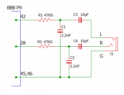
R1/C1及びR2/C2はLPF。
R1/R2は電流制限の意味もある。
C3/C4はDCカット目的のカップリングコンデンサでケミコンを用いるならば、両極性である必要がある。
J1は3.5mmステレオミニジャックDIP化キットで、秋月電子で購入できる。
この回路をブレッドボード上に組み、BBBのP9.28とP9.42にそれぞれ結線するとともに、P9.45/P9.46に接地する。
3.5mmステレオミニジャックにステレオイヤホンを接続する。
44.1KHz 16bit ステレオのwavファイルサンプルを用意する。
今回はSONYのリニアPCMサンプル音源を借用する。
SONY リニアPCMサンプル音源
debian@beaglebone:~/pru/am335x_pru_package/pru_sw/pwmdac_demo/pwmdac/obj$ cd ../ debian@beaglebone:~/pru/am335x_pru_package/pru_sw/pwmdac_demo/pwmdac$ wget http://www.sony.jp/ic-recorder/sound-compare/pcm/wav/band/middletempo/PCM-D50_441kHz16bit.wav --2015-05-09 13:13:30-- http://www.sony.jp/ic-recorder/sound-compare/pcm/wav/band/middletempo/PCM-D50_441kHz16bit.wav Resolving www.sony.jp (www.sony.jp)... 192.229.232.129 Connecting to www.sony.jp (www.sony.jp)|192.229.232.129|:80... connected. HTTP request sent, awaiting response... 200 OK Length: 7139918 (6.8M)
Saving to: `PCM-D50_441kHz16bit.wav' 100%[======================================>] 7,139,918 8.51M/s in 0.8s 2015-05-09 13:13:31 (8.51 MB/s) - `PCM-D50_441kHz16bit.wav' saved [7139918/7139918] debian@beaglebone:~/pru/am335x_pru_package/pru_sw/pwmdac_demo/pwmdac$
以上で準備は終了。
再生を行う。
root権限が必要。
debian@beaglebone:~/pru/am335x_pru_package/pru_sw/pwmdac_demo/pwmdac$ cd obj debian@beaglebone:~/pru/am335x_pru_package/pru_sw/pwmdac_demo/pwmdac/obj$ sudo ./pwmdac.out ../PCM-D50_441kHz16bit.wav WAVE size = 7139910 RIFF fmt Chank size = 16 wFormat TAG = 1 channels = 2 sample per sec = 44100 avg byte per sec = 176400 4 blocksize 16 bit per sample data data.chunkSize = 7139824 wave data length = 3569912 INFO: Executing example. pru is waiting trigger to start. [0] = 0, [1] = 1, [2] = 0, [3] = 0 debian@beaglebone:~/pru/am335x_pru_package/pru_sw/pwmdac_demo/pwmdac/obj$
無事再生された。
流石に解像度は無くなってしまっているが、思ったよりもノイズは少なく音声レベルでは十分活用できそうだ。
CRだけの追加でwavファイルの再生ができるわけだから、恐らくBBBで最もチープな音源再生方法であろう。
鳴ると思ってプログラムを組んだわけであるが、実際キチンと鳴ってくれると存外に嬉しいものだ。